C.3 SL/HL Concept 5 of 9

Single-Slit Diffraction (AHL)

Part of C.3 Wave Phenomena · Unit C — IB Physics 2023

5 Lesson 5 of 9 · C.3 Wave Phenomena
Single‑Slit Diffraction (AHL)
How light spreads after passing through a narrow opening – interference of Huygens wavelets

🎵 Everyday phenomenon – sound & radio waves

Stand near a tall building and listen to a street musician around the corner – you hear the music clearly because sound waves diffract (spread) around obstacles. Long‑wave radio signals reach valleys behind mountains, but short‑wave TV signals cannot – diffraction is strongest when the obstacle/gap size is comparable to the wavelength.

Water waves spreading through a narrow opening
Fig 1 – Water waves fan out into a semicircle after passing through a narrow gap. The narrower the gap, the stronger the diffraction.

⚡ Diagnostic quick‑check

1. Two identical waves meet so that a crest from one arrives exactly with a trough from the other. What is the resultant amplitude?
A Zero ✓
B Double
C Same as one wave
D It depends on frequency
2. Which phrase best describes “path difference”?
A The distance between two slits
B The extra distance one wave travels relative to another ✓
C Wavelength
D Slit width
Foundation – Interference & Huygens

📐 Key definitions

Coherence: two sources emit waves with same frequency and constant phase difference.
Path difference: difference in distance from a point to two sources.
Constructive interference: path difference = nλ → waves in phase → bright fringe.
Destructive interference: path difference = (n+½)λ → waves out of phase → dark fringe.

💡 The principle of superposition: resultant displacement = vector sum of individual displacements.
Ripple tank two-source interference
Fig 2 – Two‑source interference in a ripple tank. Nodal lines (dark) occur where path difference = (n+½)λ.
Huygens wavelet diagram for single slit
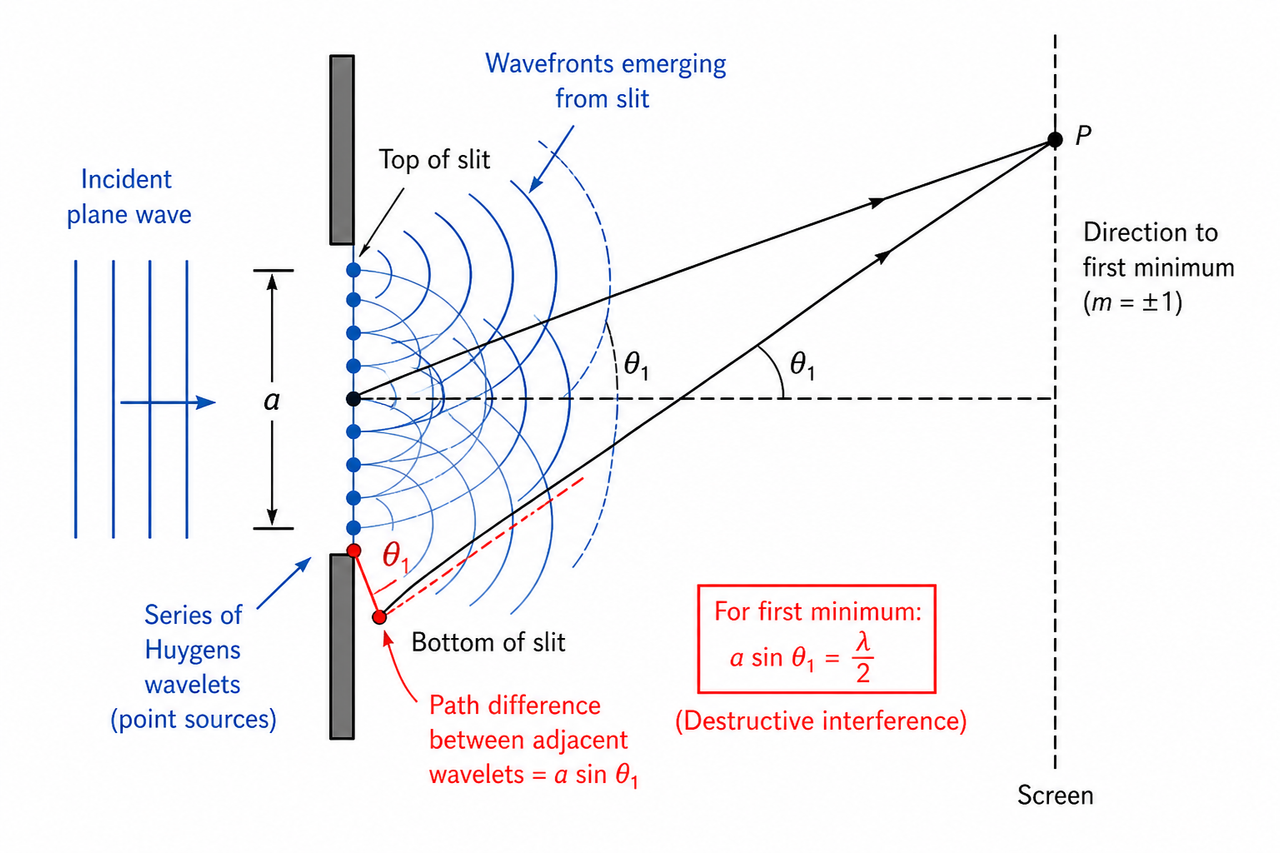
Fig 3 – Huygens’ principle: every point across the slit acts as a wavelet source. Their superposition creates the diffraction pattern.

🔬 Introducing single‑slit diffraction

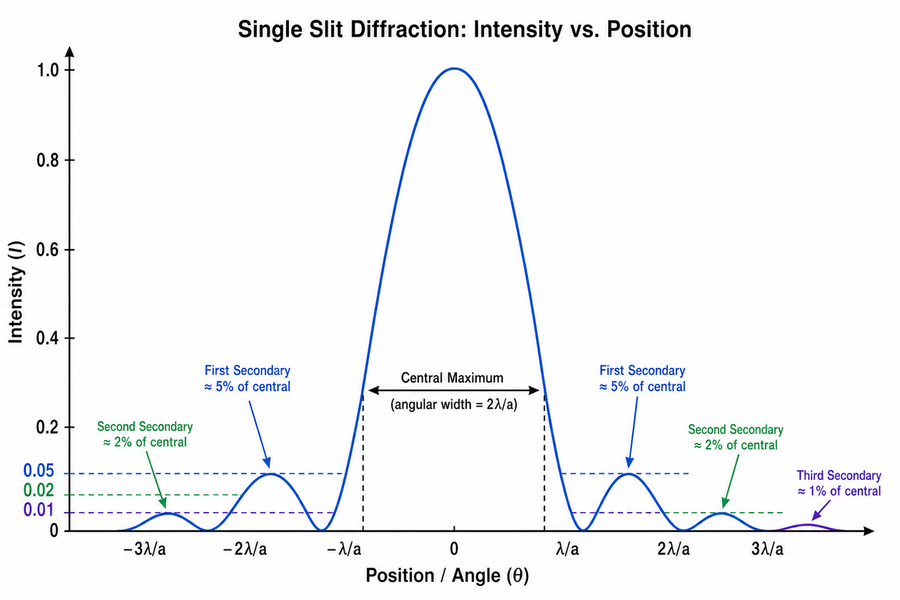
When light passes through a very narrow slit, it does not travel in a straight line but spreads out. According to Huygens, every point across the slit emits wavelets that interfere. The result is a pattern of a very bright central maximum flanked by dimmer secondary maxima, separated by completely dark minima.

Laser single-slit diffraction pattern
Fig 4 – Actual laser pattern: bright central band, weaker side lobes.
Intensity vs position graph
Fig 5 – Intensity vs position on screen. Central maximum is twice as wide as side lobes and >20× brighter than first side peak.

❓ Why minima occur – pairing wavelets

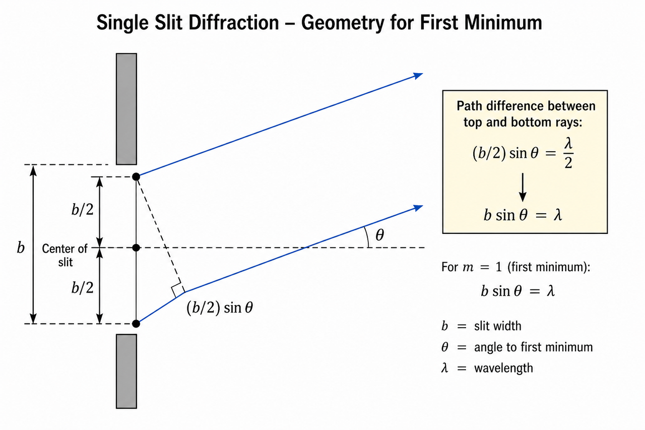
For the first dark fringe at angle θ₁, take wavelets from the top edge and the midpoint of the slit. If their path difference is λ/2, they cancel. Geometry: (b/2) sinθ₁ = λ/2 → sinθ₁ = λ/b. Extending to the whole slit gives the general condition for minima:
b sinθ = nλ  (n = 1, 2, 3, …)
Slit geometry for first minimum
Fig 6 – Deriving the first minimum: path difference between top and middle ray = λ/2.
✓ For small angles: θ ≈ λ/b (in radians). Central maximum angular width = 2λ/b.
The master formula

🔑 Single‑slit minima condition

\boxed{b \sin\theta_n = n\lambda} \quad (n = 1,2,3,\dots)

Linear width of central maximum on a screen: \( w = \frac{2\lambda D}{b} \) (for small angles).
Proportionalities: θ₁ ∝ λ and θ₁ ∝ 1/b. Narrower slit → wider pattern. Longer λ → wider pattern.

Interactive Slider Lab – Explore diffraction

🧪 Single‑slit diffraction explorer

First minimum θ₁--
Central width (mm)--
Rel. peak intensity1.00

💡 What to notice: Drag slit width – narrower → wider central peak but much dimmer. Change colour: red (long λ) spreads more than blue. Double D → pattern on screen doubles in size (angle unchanged).

Step‑by‑step worked examples

📝 Worked Example 1 – Finding slit width (IB style)

1
Given: λ = 532 nm, D = 2.50 m, distance to first minimum s = 4.0 cm.
2
Small angle: θ ≈ s/D = 0.040 m / 2.50 m = 0.016 rad.
3
First minimum condition: b sinθ = λ → b ≈ λ/θ = 532×10⁻⁹ / 0.016 = 3.33×10⁻⁵ m = 0.033 mm.
4
Answer: slit width = 0.033 mm. (If screen moved to 1.25 m, central width halves to 4.0 cm.)

📝 Worked Example 2 – Effect of wavelength change

Same slit (0.033 mm) but λ changes to 650 nm. Find new first minimum distance at D=2.50 m.

1
θ₁ = λ/b = 650×10⁻⁹ / 3.3×10⁻⁵ = 0.0197 rad.
2
s = D·θ = 2.50 × 0.0197 = 0.0493 m = 4.93 cm.
Graphical mastery – what every graph tells you
I vs θ
Graph 1 – I vs θ: central peak twice as wide as side lobes, zeros at nλ/b.
Graph 4 – θ₁ vs 1/b: straight line slope = λ.

📈 Linearising graphs – exam tricks

Plotting θ₁ (rad) against 1/b (mm⁻¹) gives a line through origin with slope = λ (in metres). Also w (central max width) vs D gives slope = 2λ/b.

How you will be tested
1. Monochromatic light of wavelength λ passes through a slit of width b. Which change increases the angular separation between adjacent minima?
A Moving screen further away
B Decreasing slit width b ✓
C Using shorter wavelength
D Increasing intensity
2. In a single‑slit experiment, the first secondary maximum has intensity approximately what percentage of the central maximum?
A 50%
B 25%
C 5% ✓
D 0%
3. The central maximum in a single‑slit pattern has angular width 0.04 rad. The angular width of the first subsidiary maximum (on one side) is:
A 0.02 rad ✓
B 0.04 rad
C 0.08 rad
D 0.01 rad

✍️ Fill in the blanks

For a single slit of width 0.10 mm and light of wavelength 500 nm, the first diffraction minimum occurs at sinθ = .
As the slit width is reduced, the diffraction pattern becomes and the peak intensity .
Exam question · Explain & calculate
(c) A student uses light of wavelength 633 nm and a slit of unknown width. The screen is 1.80 m away. She measures the width of the central bright fringe as 12.6 mm.
(i) Calculate the angle of the first minimum.
(ii) Determine the slit width.
(iii) The slit is replaced by one half the width. State and explain what will happen to the width of the central maximum and its brightness. [5 marks]
✓ (i) half width = 6.3 mm → θ ≈ 6.3 mm / 1800 mm = 3.5×10⁻³ rad.
✓ (ii) b = λ/θ = 633×10⁻⁹ / 3.5×10⁻³ = 1.81×10⁻⁴ m = 0.18 mm.
✓ (iii) Central maximum doubles in linear width (θ ∝ 1/b). Brightness drops to about one‑quarter because amplitude halves ⇒ intensity ∝ amplitude².
Trap corner – common mistakes

❌ “Diffraction is separate from interference”

✅ Single‑slit diffraction is interference of many wavelets from the same slit.

❌ “Wider slit → wider pattern”

✅ Wider slit → narrower pattern because θ₁ = λ/b decreases.

❌ “b sinθ = nλ gives bright fringes”

✅ This equation gives dark fringes (minima). Bright maxima are approximately halfway between.

❌ “Changing screen distance changes angles”

✅ Angles depend only on b and λ; D only changes linear size on screen.

One‑page summary
b sinθ = nλ (minima)θ₁ ≈ λ/bw = 2λD/bI ∝ b²

Central maximum contains >90% of energy. First side peak ≈5% of central. Narrow slit → wide, dim pattern; long λ → wide pattern.

Score: 0 pts