B.5 SL/HL Concept 4 of 7

Series and Parallel Circuits

Part of B.5 Current and Circuits · Unit B — IB Physics 2023

4 Lesson 4 of 7 · B.5 Current and Circuits
Series and Parallel Circuits
Two rules for how current and voltage share themselves out — one for components strung one after another, one for components wired side by side. Almost every circuit you'll meet is built from these two patterns.

🎄 Hook – the string of lights that all go dark together

Old-style decorative light strings are wired in series: if one bulb blows, the current path is broken and every bulb on the string goes dark. Modern strings are wired in parallel: each bulb sits on its own branch across the same two wires, so one failed bulb only kills itself — the rest stay lit. The wiring pattern, not the bulbs, decides what happens when one component fails.
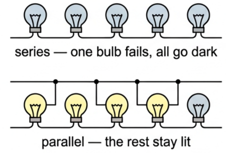
Two light strings compared: a series string with all bulbs dark after one fails, and a parallel string with one bulb dark and the rest still lit
Fig 1 — One failed bulb in series takes out the whole string; in parallel, the other branches don't even notice.
💡 Diagnostic question — why does removing one bulb from a parallel string not stop current flowing to the others? Each bulb is connected directly across the same two supply wires, on its own separate path. Removing one branch doesn't break the paths belonging to the others — current can still complete a full loop through every remaining bulb.

➡️ Series circuits: one path for the current

Series connection: two or more components connected so that there is only one path for the current, which is the same through all of them. Because charge is conserved, the charge per second (current) flowing into each component must equal the current flowing out of it and into the next — there's nowhere else for it to go.

Current in series $$I = I_1 = I_2 = \ldots$$

Each component uses up some of the available potential difference driving the current round the circuit, so the separate p.d.s must add up to the p.d. across the whole combination:

Potential difference in series $$V = V_1 + V_2 + \ldots$$

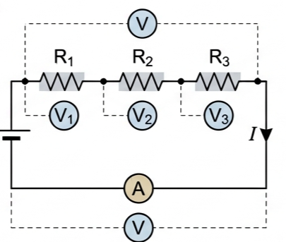
Substituting \(V=IR\) for each resistor into \(V=V_1+V_2+\ldots\) gives \(IR_{\text{s}} = IR_1 + IR_2 + IR_3\). The current \(I\) is the same throughout, so it cancels, leaving the resistance of a single resistor \(R_{\text{s}}\) that would behave exactly like the whole combination:
Total resistance in series $$R_{\text{s}} = R_1 + R_2 + \ldots$$
Three resistors R1, R2, R3 connected in series with a voltage source, ammeter and voltmeters across each resistor
Fig 2 — Resistors in series (Fig B5.27). Current is the same everywhere on the loop; each voltmeter reads a share of the total p.d.

⑂ Parallel circuits: many paths, same p.d.

Parallel connection: two or more components connected between the same two points, so they all have the same potential difference across them.

Potential difference in parallel $$V = V_1 = V_2 = \ldots$$

Conservation of charge means the current splits at the junction and recombines afterwards, so the total current supplied equals the sum of the branch currents:

Current in parallel $$I = I_1 + I_2 + \ldots$$

Applying \(I=V/R\) to every branch, \(V/R_{\text{p}} = V/R_1 + V/R_2 + V/R_3\). Every term shares the same \(V\), so it cancels, leaving the equation for the single resistor \(R_{\text{p}}\) equivalent to the whole combination:
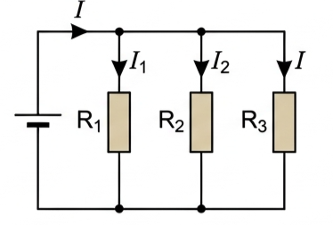
Total resistance in parallel $$\frac{1}{R_{\text{p}}} = \frac{1}{R_1} + \frac{1}{R_2} + \ldots$$
Three resistors R1, R2, R3 connected in parallel between the same two nodes, with the total current splitting into three branch currents
Fig 3 — Resistors in parallel (Fig B5.28). All three share the same p.d.; the supply current is the sum of the branch currents.

All the sockets and appliances in a house are wired in parallel: each one gets the full supply voltage regardless of what else is switched on, and each can be switched independently without affecting the others.

⚖️ Kirchhoff's laws — the two rules made formal

Kirchhoff's first law (current/junction law): at any junction, the total current entering equals the total current leaving. This is just conservation of charge applied at a point — it's what forces \(I=I_1+I_2+\ldots\) in a parallel combination.

Kirchhoff's second law (voltage/loop law): around any closed loop, the sum of the potential differences is zero. This is conservation of energy — it's what forces \(V=V_1+V_2+\ldots\) in a series combination.

🔗 Nature of Science — conservation of charge and conservation of energy aren't special rules for circuits; they're two of the most fundamental principles in all of science, also used to explain ion movement across cell membranes and energy transfers in natural systems generally.

🔬 Tool 3: how many significant figures does "5000 Ω" have?

Without more context, you can't tell. If 5000 and 8000 are exact mathematical values, every figure is significant. If they're measurements, the number of significant figures depends on the uncertainty in the measurement — which isn't visible from the digits alone. Scientific notation removes the ambiguity: \(5.00\times10^3\ \Omega\) is unmistakably three significant figures, while \(5\times10^3\ \Omega\) is one.

For the numerical data in this course, the rule is simple: unless told otherwise, assume every digit given is significant.

📈 Graph mastery — resistance versus number of resistors

Graph typeAxes (X, Y)ShapeWhat to read
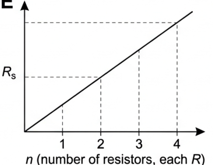
Total resistance vs number in seriesn (identical resistors, each R) · RsStraight line through the originGradient = R; each extra resistor adds a fixed R to the total
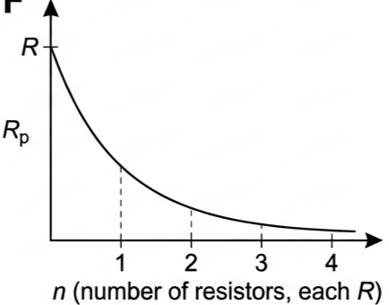
Total resistance vs number in paralleln (identical resistors, each R) · RpFalls steeply from R at n=1, curving down towards zeroRp = R/n; adding branches always makes the combination easier to conduct through, never harder
Graph of total resistance against number of identical resistors in series, a straight line through the origin
Fig 5 — Adding identical resistors in series: Rs grows in equal steps of R.
Graph of total resistance against number of identical resistors in parallel, a curve decreasing from R towards zero
Fig 6 — Adding identical resistors in parallel: Rp always falls, and stays below the smallest single resistor.

✍️ Worked example 1 – 5000 Ω and 8000 Ω resistors

A 5000 Ω resistor and an 8000 Ω resistor are connected first in series, then in parallel, with a 4.5 V battery. Find, for each arrangement: the combined resistance; the current through each resistor; the p.d. across the 5000 Ω resistor.

1
Identify: series first — same current through both, resistances add. Then parallel — same p.d. across both, reciprocals add.
2
Data: \(R_1=5000\ \Omega\), \(R_2=8000\ \Omega\), \(V=4.5\) V.
3
Equation — series:
\(R_{\text{s}} = 5000+8000 = 13000\ \Omega\)
\(I = V/R_{\text{s}} = 4.5/13000\)
Equation — parallel:
\(1/R_{\text{p}} = 1/5000+1/8000 = 13/40000\)
\(R_{\text{p}} = 40000/13\)
4
Answer — series: \(R_{\text{s}}=13\,000\ \Omega\); \(I=3.5\times10^{-4}\) A through both resistors; \(V(5000\ \Omega)=IR=1.7\) V.
Answer — parallel: \(R_{\text{p}}=3100\ \Omega\); both resistors have the full 4.5 V across them; \(I(5000\ \Omega)=4.5/5000=9.0\times10^{-4}\) A; \(I(8000\ \Omega)=4.5/8000=5.6\times10^{-4}\) A.

✍️ Worked example 2 – five lamps (B5.5)

Lamps A and B are in series in the main circuit. Between them the circuit splits into two parallel branches: lamps C and D in series with each other, and lamp E alone. All five lamps are identical. (a) Compare the brightness of all five lamps. (b) If each lamp has a constant resistance of 2.0 Ω, find the total resistance of the circuit.

1
Identify: A and B carry the full circuit current (series). That current splits between the C–D branch and the E branch (parallel), so A and B must be brighter than C, D and E.
2
Data (b): each lamp \(R=2.0\ \Omega\). C and D are in series with each other: \(R_{\text{CD}} = 2.0+2.0 = 4.0\ \Omega\). This is in parallel with E.
3
Equation (b):
\(1/R_{\text{CD‖E}} = 1/4.0 + 1/2.0\)
\(R_{\text{CD‖E}} = 4/3 = 1.3\ \Omega\)
Total: \(R_{\text{total}} = R_{\text{A}}+R_{\text{B}}+R_{\text{CD‖E}}\)
4
Answer (a): A and B are equally bright (same current, in series). C and D are equally bright as each other, but dimmer than A and B. E is brighter than C or D, because more current flows through the single lamp E than through either of the two lamps sharing the C–D branch.
Answer (b): \(R_{\text{total}} = 2.0+2.0+1.3 = 5.3\ \Omega\).
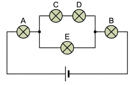
Circuit with five lamps: A and B in series in the main path, with C and D in series forming one parallel branch and E alone forming the other
Fig 4 — Five-lamp circuit (Fig B5.29). A and B share the full current; it then splits between the C–D branch and lamp E.

🏠 Real-world: why your house is wired in parallel

If household appliances were wired in series, switching off one lamp would cut the current to every other appliance in the house, and every device would have to share the mains voltage between them. Parallel wiring gives every socket the full supply voltage and lets each device be switched on or off without touching any of the others.

✓ Examiner tip: if asked why household circuits use parallel wiring, name both reasons — full supply voltage to each device, and independent switching — a one-reason answer usually drops a mark.

🚀 HL extension – solving combination circuits

Most real circuits are neither purely series nor purely parallel — they're built from both. The strategy is always the same: find a parallel (or series) section that reduces to a single equivalent resistor, replace it with that one resistor, and repeat until the whole network is one simple series chain.

Challenge: in the five-lamp circuit above, why can't you just add all five resistances together to get the total? Answer: R = R1+R2+… only applies to resistors genuinely in series — C, D and E are not all in series with each other, since C+D and E form two separate parallel paths. You must collapse that parallel section to one equivalent resistor first, then add it to A and B in series.

⚠️ Trap corner – common mistakes

MisconceptionCorrect view
Voltage is the same through every component, whatever the circuitCurrent is the same in series; voltage is the same in parallel. Mixing these up is the single most common circuits error
Adding resistors in parallel always increases the total resistanceExtra parallel branches give current more ways to flow, so total resistance always decreases and stays below the smallest branch resistance
An ammeter and voltmeter can go anywhere in a circuitAn ammeter must be in series (same current as the component); a voltmeter must be in parallel (same p.d. as the component). Swapping them changes the readings completely
Rp = R1+R2 for parallel resistors, same formula as seriesParallel uses reciprocals: 1/Rp = 1/R1+1/R2+…, and Rp must come out smaller than the smallest individual resistor
⚠️ Most common exam slip: writing \(1/R_{\text{p}} = 1/R_1+1/R_2\) and then forgetting to take the reciprocal again at the end — the sum gives \(1/R_{\text{p}}\), not \(R_{\text{p}}\) itself.
series: I same, V adds parallel: V same, I adds Rs = R1+R2+… 1/Rp = 1/R1+1/R2+… Kirchhoff 1: charge conservation Kirchhoff 2: energy conservation ammeter in series voltmeter in parallel
Practice check — multiple choice
1. Three identical resistors, each of resistance R, are connected in parallel. The combined resistance is
A 3R
B R
C R/3
D 9R
2. In a series circuit containing two resistors, which quantity must be the same through both of them?
A Potential difference
B Current
C Power
D Resistance
3. Kirchhoff's second law (the voltage/loop law) is a direct consequence of conservation of
A Charge
B Energy
C Mass
D Momentum
4. All the sockets and appliances in a house are wired in parallel mainly because
A It uses less wire overall
B Each device gets the full supply voltage and can be switched independently
C It makes the total resistance of the house larger
D It makes the current the same through every appliance
Practice check — fill in the blanks

Complete the statements:

In a series circuit, the current is the through every component, while in a parallel circuit it is the potential difference that is the same across every . The total resistance of resistors in series is found by the individual resistances. For resistors in parallel, the of the total resistance equals the sum of the reciprocals of the individual resistances. Kirchhoff's first law follows from conservation of , and Kirchhoff's second law follows from conservation of .
Exam‑style questions
Exam question · Draw
Q23. Draw a circuit diagram to represent the following arrangement: two lamps, A and B, are connected to a 12 V battery with a switch such that it can control lamp A only (lamp B is always on). An ammeter is connected so that it can measure the total current in both lamps and a voltmeter measures the p.d. across the battery. [3 marks]
✓ Lamps A and B each on their own branch, both connected across the battery (parallel with each other), so B stays lit regardless of A.
✓ Switch S placed in series with lamp A only, inside A's branch — opening S turns off A without affecting B.
✓ Ammeter placed in the main line, in series with the battery before the branches split, so it reads the total current in both lamps; voltmeter connected directly across the battery terminals, in parallel with the whole circuit.
Exam question · Calculate
Q24. Calculate the four possible total resistances that can be made by combining three 10 Ω resistors. [3 marks]
✓ All three in series: \(10+10+10 = 30\ \Omega\).
✓ All three in parallel: \(1/R = 3/10\), so \(R = 3.3\ \Omega\).
✓ Two in parallel, that combination in series with the third: \((10\times10)/20 + 10 = 5+10 = 15\ \Omega\).
✓ Two in series, that combination in parallel with the third: two in series \(=20\ \Omega\); \((10\times20)/30 = 6.7\ \Omega\).
Exam question · Predict / Explain
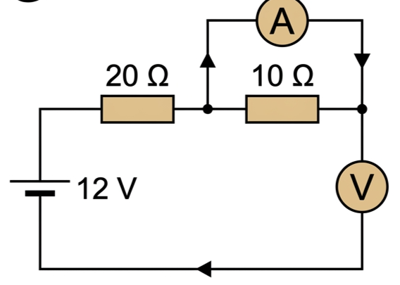
Q25. Figure B5.30 shows a simple circuit (12 V battery, a 20 Ω resistor and a 10 Ω resistor in series) in which the ammeter and voltmeter have been connected in the wrong positions — the ammeter in parallel with the 10 Ω resistor, and the voltmeter in series with it. (a) Predict the readings you would expect on the meters. Explain your answer. (b) When the meters are swapped into their correct positions, what readings would you expect? [4 marks]
12 V circuit with a 20 ohm and 10 ohm resistor in series, with an ammeter wrongly connected in parallel with the 10 ohm resistor and a voltmeter wrongly connected in series with it
Fig 7 — Fig B5.30: ammeter and voltmeter connected in the wrong positions.
✓ (a) An (almost ideal) ammeter has near-zero resistance, so placing it in parallel with the 10 Ω resistor short-circuits that resistor. Virtually all the current takes the ammeter's zero-resistance path, so the ammeter reads close to \(12/20 = 0.6\) A — the current for the 20 Ω resistor alone.
✓ The voltmeter, in series with the (now short-circuited) 10 Ω resistor, has a very high resistance, so almost no current flows down that branch — it reads close to 0 V.
✓ (b) Correctly positioned (ammeter in series, voltmeter in parallel with the 10 Ω resistor): total \(R = 30\ \Omega\), so \(I = 12/30 = 0.4\) A (ammeter reading) and \(V = IR = 0.4\times10 = 4.0\) V (voltmeter reading).
Exam question · Determine
Q26. (a) Calculate the current that flows through a 12.0 Ω resistor connected to a p.d. of 9.10 V. (b) An ideal ammeter would display this current accurately, but what value will an ammeter of resistance 0.31 Ω record? (c) Determine the percentage error when using the ammeter in this way. [4 marks]
✓ (a) \(I = V/R = 9.10/12.0 = 0.758\) A.
✓ (b) The ammeter's own resistance adds to the circuit: \(I = 9.10/(12.0+0.31) = 9.10/12.31 = 0.739\) A.
✓ (c) Percentage error \(= \dfrac{0.739-0.758}{0.758}\times100 = -2.5\%\) — the ammeter reads about 2.5% low.
Exam question · Determine
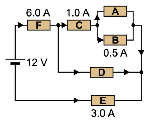
Q27. Figure B5.31 shows a 12 V circuit with resistors A–F. The total current from the battery is 6.0 A, flowing through resistor F. It splits: 1.0 A flows through resistor C, which then splits into branches through A and B (with 0.5 A through B); a middle branch through resistor D carries current I2; a bottom branch through resistor E carries 3.0 A; the currents recombine to give I3. (a) Determine the currents I1, I2 and I3. (b) If C = 5.0 Ω and E = 2.0 Ω, determine values for the four unknown resistances A, B, D and F. [6 marks]
Circuit diagram with resistors A to F: 6.0 A through resistor F splitting into a branch through C then A and B, a middle branch through D, and a bottom branch through E carrying 3.0 A, recombining afterwards
Fig 8 — Fig B5.31: three parallel branches (C→A/B, D, E) between resistor F and the recombination point.
✓ (a) The three branches (C→A/B, D, E) are in parallel, so their currents sum to the total 6.0 A: \(1.0+I_2+3.0 = 6.0\), giving \(I_2 = 2.0\) A. Since A and B split the 1.0 A equally (B = 0.5 A), \(I_1 = 0.5\) A. All branch currents recombine before F, so \(I_3 = 6.0\) A.
✓ (b) All three parallel branches share the same p.d., equal to the p.d. across E: \(V = I_{\text{E}}R_{\text{E}} = 3.0\times2.0 = 6.0\) V.
✓ Branch C+A‖B: \(V_{\text{C}} = 1.0\times5.0 = 5.0\) V, leaving \(6.0-5.0=1.0\) V across A‖B, so \(R_{\text{A}} = R_{\text{B}} = 1.0/0.5 = 2.0\ \Omega\).
✓ Branch D: \(R_{\text{D}} = 6.0/2.0 = 3.0\ \Omega\).
✓ F carries the full 6.0 A and drops the remaining \(12-6.0=6.0\) V, so \(R_{\text{F}} = 6.0/6.0 = 1.0\ \Omega\).
Exam question · Determine
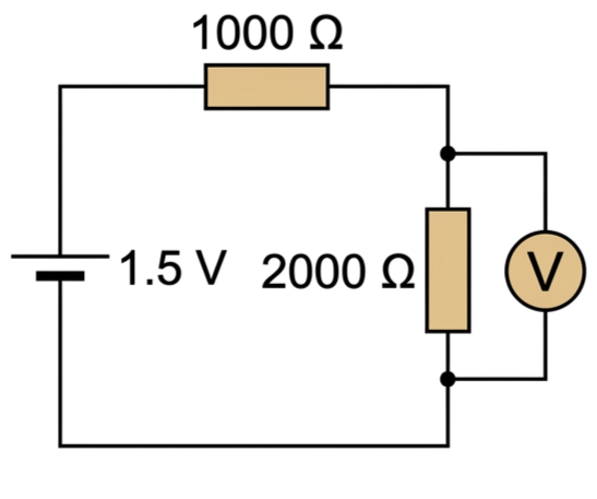
Q28. Figure B5.32 shows a 1.5 V battery connected in series with a 1000 Ω resistor and a 2000 Ω resistor. A voltmeter is connected across the 2000 Ω resistor. (a) Calculate the current in the circuit before the voltmeter is connected. (b) What is the voltage across the 2000 Ω resistor before the voltmeter is connected? (c) Determine the voltages that will be measured if voltmeters with the following resistances are connected in turn across the 2000 Ω resistor: (i) 5000 Ω, (ii) 50 000 Ω. [5 marks]
1.5 volt battery in series with a 1000 ohm resistor and a 2000 ohm resistor, with a voltmeter connected across the 2000 ohm resistor
Fig 9 — Fig B5.32: a real voltmeter's own resistance loads the circuit it's measuring.
✓ (a) \(I = V/(R_1+R_2) = 1.5/3000 = 5.0\times10^{-4}\) A.
✓ (b) \(V_2 = IR_2 = 5.0\times10^{-4}\times2000 = 1.0\) V.
✓ (c)(i) 2000 Ω ‖ 5000 Ω \(= 1429\ \Omega\); total \(R = 2429\ \Omega\); \(I = 1.5/2429\); \(V = I\times1429 = 0.88\) V.
✓ (c)(ii) 2000 Ω ‖ 50 000 Ω \(= 1923\ \Omega\); total \(R = 2923\ \Omega\); \(I = 1.5/2923\); \(V = I\times1923 = 0.99\) V — closer to the ideal 1.0 V, because a higher-resistance voltmeter draws less current away from the branch it's measuring.
Score: 0 pts